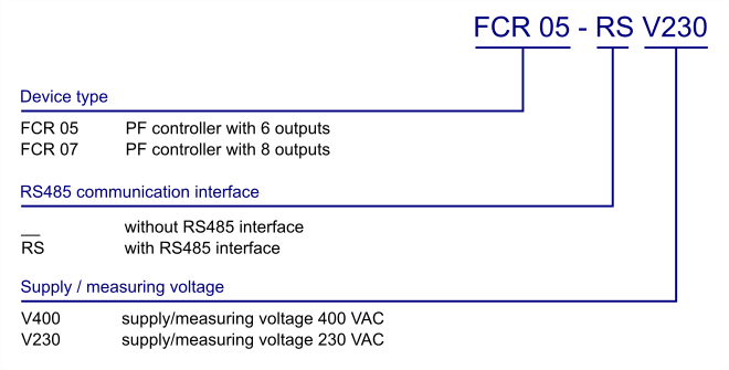
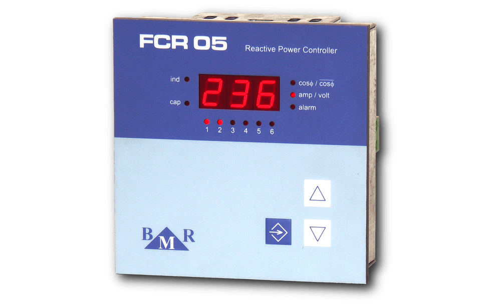
PF Controller FCR05 & FCR07
Power factor controllers FCR05 and FCR07 are 4 quadrant controllers designed for low voltage applications. The design gives possibility to control up to 6 compensation stages for FCR05 and up to 8 stages for FCR07 regulator. Last output can be programmed to be used as an alarm output or as a normally regulated compensation stage.
- 4 quadrant measurement and regulation
- designed for LV and MV PFC based on contactors
- ready for de-compensation reactor usage
- automatic detection of measuring circuit
- automatic detection of capacitor steps
- high sensitivity of current measuring input (2 mA)
- strong imunity agains high harmonic polution
- 6 or 8 regulated outputs
- three regulation methods for various nation rules
- logging memory of min and max values
- logging of operation number and time of each step
- communication interface RS485
- Modbus RTU communication protocol
- internal temperature sensor
- panel mounting design 96 x 96 mm
- PC SW for configuration and monitoring
Function
Device digitizes measured phase voltage and current in one phase. Then, from those values, parameters like: power factor, effective values of voltage and current, apparent power and reactive power, are calculated. With consideration of requested cosφ it calculated need compensation power. According to its size, regulator switches on or off appropriate capacitor stages.
Within the scope of each power level, regulator uses method of circle switching. All the time connects this stage at appropriate power level which was switched off for longest time. Everything is made so that regulator will reach optimal compensation in one regulation cycle with minimum number of switched stages.
Alarms
Circular switching
Software
Technical features
| Parameter | Value |
|---|---|
| supply voltage | 400 V AC 50 Hz (+10%, -20%) |
| measuring voltage range | 400 V AC 50 Hz (+10%, -20%) |
| system frequency | 50 / 60 Hz |
| measuring current range | 0.01 ... 5.3 A |
| self consumption | 10 VA |
| number of regulated outputs | 6 or 8 |
| alarm output | last step |
| output contact load |
250 VAC / 5A |
| range of regulated PF | 0.8 L ... 0.8 C |
| capacitor step settings | manual / automatic |
| ambient temperature | -40°C ... +70°C |
| front panel | 97 x 97 mm |
| panel cutout | 91 x 91 mm |
| installation depth | 55 mm |
| weight | 650 g |
| protection degree |
IP20 read side / IP54 front panel |